
Introduction
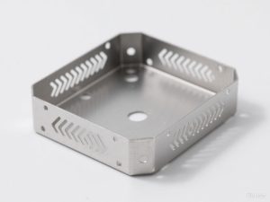
Have you ever experienced the frustration of carefully machining a delicate aluminum enclosure, only to find it warped like a potato chip when you release it from the fixture? Or perhaps you’ve seen thin titanium features that should be straight, but instead exhibit a noticeable “bell mouth” effect? In precision CNC machining, thin-wall part distortion represents one of the most challenging yet common obstacles, affecting industries from aerospace to consumer electronics.
The problem is fundamental: when material is removed, the internal stresses within the raw stock seek a new equilibrium, causing deformation. For thin walls (typically with an aspect ratio greater than 10:1, height to thickness), this effect is magnified. They lack the structural rigidity to resist cutting forces, vibration (chatter), and the internal stresses being released.
This comprehensive guide moves beyond simply identifying the problem. We will explore a systematic, multi-faceted defense against distortion, covering everything from the initial fixturing strategy for delicate components to the final finishing pass. By implementing these solutions, you can transform thin-walled machining from a gamble into a reliable, repeatable process.
Phase 1: The Foundation – Strategic Fixturing and Workholding
A successful thin-wall machining operation begins long before the spindle starts. How you hold the part is paramount.
1. Embrace “Onion Skin” Machining
Do not machine the part to its final dimensions in one go, completely freeing it from the stock. Instead, leave a uniform residual “skin” of material (e.g., 1-2 mm) connecting the delicate features to the more rigid core of the raw stock or a dedicated fixture tab. This skin maintains rigidity during the bulk of the machining. Only in the final, light finishing passes do you carefully cut this skin away.
2. Optimize Fixture Design
- Conformal Fixturing: Use a fixture that supports the entire backside of the thin-wall area, often with a low-melting-point alloy (like CerroSafe) or a specialized vacuum chuck. This provides continuous, uniform support against cutting forces.
- Vacuum Chucking: Ideal for large, flat thin-wall parts like aerospace skin panels. It distributes holding force evenly, minimizing point loads that can cause local distortion.
- Strategic Tab Locations: When using tabs, place them at nodal points (points of least expected vibration) and ensure they are thick enough to provide support but placed in areas easy to finish post-machining.
3. Material Stress-Relief
For critical components, specify pre-machined material that has been stress-relieved by the supplier. Alternatively, perform a rough machining pass, then stress-relieve the part, and finally complete the finishing passes. This allows the material to “move” before you create the final, precise geometries.
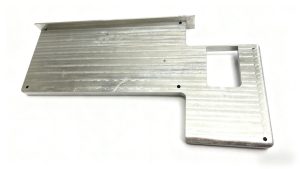
Phase 2: The Battle Plan – Toolpath Strategy & Programming
Your CAM programming strategy is your primary tool for managing cutting forces and heat.
1. The Principle of Symmetrical Material Removal
Imagine a thin rib. If you machine all material from one side first, the unbalanced stress will pull it like a bow. The solution is balanced machining:
- Machine both sides of a wall alternately, removing similar volumes of material in a mirrored sequence.
- For a pocket surrounded by thin walls, use a “trochoidal” or “morphing” toolpath that spirals evenly from the center, rather than clearing one side completely before moving to the next.
2. Climb Milling is Non-Negotiable
Always use climb milling (down milling). In this direction, the cutter tooth engages the material at its maximum thickness and exits at zero, pushing the part into the fixture. Conventional milling lifts and deflects the thin wall.
3. Optimal Toolpath Selection
- Finishing Passes: Use high-speed machining (HSM) strategies. These employ small stepovers (5-10% of tool diameter) and consistent, light radial engagement to maintain a constant cutter load, minimizing deflection and heat generation.
- Avoid “Plunging” on Walls: Never use a straight plunging move on or near a thin feature. Always ramp or helix into the cut.
- Multiple Spring Passes: Program several identical finishing passes (“spring passes”). The first pass relieves stress and may cause slight movement; the second and third passes clean up the resulting deviation with minimal load.
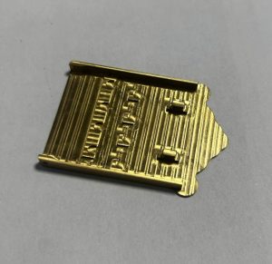
Phase 3: The Execution – Tooling and Cutting Parameters
The right tool, run with the right parameters, makes the final difference.
1. Tool Selection for Thin-Wall Machining
- Sharpness & Geometry: Use tools with a sharp, polished cutting edge and a high positive rake angle to slice cleanly with less downward force.
- Stiffness is Key: Maximize tool diameter and shank size. Use the shortest possible flute length and overall tool projection to minimize deflection. A long-reach, variable-helix end mill is better than a standard long tool.
- Specialized Tooling: Consider tools designed for high-flexibility materials, often featuring a reduced neck diameter (for clearance) but a full-diameter cutting edge for strength.
2. Dialing in the Perfect Cut
- High RPM, Moderate Feed: A high surface speed helps produce a clean shear. Use a moderate-to-high feed rate per tooth to ensure the tool is cutting, not rubbing, which generates heat.
- Light Axial Depth of Cut (DOC): For finishing, use a light DOC (e.g., 0.1-0.5mm). You can achieve total depth with multiple step-downs.
- Aggressive Radial Stepover Reduction: This is the most critical parameter. For finishing, a 3-5% stepover of the tool diameter drastically reduces radial force. The tool’s corner radius, not its full side, does the work.
- Coolant Strategy: Use high-pressure through-tool coolant (if available) to evacuate chips from deep pockets and keep the cut cool. For aluminum, a well-directed flood or mist is essential to prevent heat buildup and material adhesion.
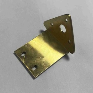
Phase 4: Special Considerations for Specific Materials
- Aluminum (e.g., 6061, 7075): Prone to thermal expansion and built-up edge. Focus on sharp tools, high-pressure coolant, and controlling heat.
- Titanium (Ti6Al4V): Poor thermal conductivity leads to heat concentration at the cutting edge. Use lower surface speeds, consistent feed to avoid work hardening, and generous coolant.
- Plastics (e.g., PEEK, Delrin): Highly elastic and prone to spring-back. Use razor-sharp tools, high RPM, light feeds, and consider cryogenic cooling to maintain rigidity.
Conclusion: A Philosophy of Gentle Precision
Machining thin walls successfully requires a shift in mindset: from forceful material removal to gentle, strategic persuasion. It’s an integrated system where fixture design informs programming, and tool selection enables perfect parameters.
There is no single “magic bullet.” The solution lies in stacking multiple best practices—symmetrical fixturing, balanced toolpaths, optimized tools, and precise parameters—to create a cumulative effect of stability and control.
At our precision machining facility, we confront these challenges daily, from crafting intricate aerospace ductwork to delicate medical device housings. We combine advanced CAM software, high-performance machine tools, and deep process expertise to deliver complex, thin-walled components that hold true to their design intent.
Ready to conquer your thin-wall machining challenges? Let our engineering team provide a free DFM (Design for Manufacturability) analysis on your next part drawing, with specific recommendations to prevent distortion from the start.