
Why Your Tool Choice Matters More Than You Think
Every day in CNC shops around the world, a critical decision happens hundreds of times: which cutting tool to use for the job. Get it right, and parts come out perfect, machines run smoothly, and costs stay low. Get it wrong, and you face scrapped parts, machine downtime, and frustrated operators.
At Lenchor Precision, we’ve machined everything from delicate medical components to robust aerospace parts. Through thousands of hours of machining, we’ve learned that tool selection isn’t just technical—it’s strategic. It affects your part quality, production speed, and most importantly, your bottom line.
The Three Pillars of Smart Tool Selection
1. Material Match: Speaking the Same Language
Different materials speak different “languages” to your tools. What works for aluminum will fail miserably with stainless steel.
For Aluminum and Soft Metals:
- Use sharp, polished tools with high helix angles
- Carbide with TiAlN coating works beautifully
- High speeds and feeds are your friends
- Watch for built-up edge (material sticking to the tool)
For Stainless Steel (304/316):
- Tougher carbide grades are essential
- Moderate helix angles prevent chatter
- Consistent, controlled feeds prevent work hardening
- Chip breaking geometry becomes critical
For Engineering Plastics (POM, Bakelite, Polyurethane):
- Extremely sharp cutting edges prevent melting
- Positive rake angles for clean shearing
- Coolant or air blast to manage heat
- Special attention to preventing delamination
2. Operation Type: Right Tool for the Right Job
Just as you wouldn’t use a screwdriver to hammer a nail, you need to match tools to operations.
Roughing Operations:
- Strong, durable tools with reinforced corners
- Higher feed rates to maximize material removal
- Chip evacuation is priority one
- Tools designed to handle interrupted cuts
Finishing Operations:
- Precision-ground tools for superior surface finish
- Sharp edges for clean cutting
- Tools designed for consistent dimensional accuracy
- Special attention to corner radii and edge preparation
Special Operations (like thin-wall machining or Swiss turning):
- Specialized tool geometries for specific challenges
- Tools optimized for vibration resistance
- Customized coatings for particular materials
- Length-to-diameter ratios designed for stability
3. Machine Capability: Working Within Your System
The most advanced tool in the world won’t help if your machine can’t handle it.
For 3-Axis Machining Centers:
- Standard length tools for maximum rigidity
- Tools optimized for typical spindle speeds
- Consideration for reach and clearance angles
For Swiss-Type Lathes:
- Compact tools for confined spaces
- Tools designed for simultaneous operations
- Special attention to tool pressure and deflection
For High-Speed Machining:
- Balanced tools for vibration-free operation
- Special coatings for heat management
- Tools designed for rapid acceleration/deceleration
The Hidden Language of Tool Wear: What Your Tools Are Trying to Tell You
Tools don’t fail suddenly—they give warnings. Learning to read these signs separates amateur machinists from true professionals.
Early Stage Wear: The Subtle Signs
Flank Wear:
- What it looks like: Small, uniform wear land on tool flank
- What it means: Normal, progressive wear
- When to act: Monitor growth rate
- Acceptable limit: 0.3mm for finishing, 0.6mm for roughing
Crater Wear:
- What it looks like: Depression on tool face
- What it means: Chemical interaction with material
- When to act: When crater depth reaches half of edge thickness
- Prevention: Adjust speeds or try different coating
Problem Signs: When Things Are Going Wrong
Built-Up Edge:
- What it looks like: Material welded to cutting edge
- What it means: Speed too low or wrong tool material
- Immediate action: Increase speed or use sharper tool
- Common with: Aluminum and sticky materials
Chipping:
- What it looks like: Small pieces missing from edge
- What it means: Impact or vibration issues
- Immediate action: Check fixturing, reduce feed, or use tougher tool
- Common with: Interrupted cuts or hard materials
Thermal Cracking:
- What it looks like: Cracks perpendicular to cutting edge
- What it means: Thermal cycling from coolant on/off
- Immediate action: Use consistent coolant application
- Common with: High-temperature alloys

Critical Failure Signs: Stop Immediately
Catastrophic Failure:
- What it looks like: Tool broken in multiple pieces
- What it means: Multiple parameters wrong or tool defect
- Immediate action: Stop machine, inspect workpiece and machine
- Prevention: Better monitoring and conservative parameters
Notching:
- What it looks like: Deep groove at depth of cut line
- What it means: Work hardening or abrasive material
- Immediate action: Change depth of cut or tool geometry
- Common with: Stainless steel and hardened materials
Our Practical Tool Management System
After years of machining precision components for medical devices, robotics, and aerospace applications, we’ve developed a systematic approach to tool management.
Step 1: Initial Tool Selection Protocol
When we receive a new part drawing, we follow this decision process:
- Material Analysis: What are we cutting?
- Feature Analysis: What operations are needed?
- Quality Requirements: What surface finish and tolerances?
- Quantity Considerations: Prototype or production run?
- Machine Assignment: Which machine will run this job?
Step 2: Setup and Testing Protocol
Before any production run begins:
- Tool Inspection: Verify each tool under magnification
- Test Cut: Machine sample and measure results
- Parameter Optimization: Adjust speeds and feeds based on results
- Documentation: Record successful parameters for future use
Step 3: In-Process Monitoring
During production:
- First-Piece Inspection: Comprehensive check of initial parts
- Periodic Checks: Scheduled tool inspection intervals
- Operator Feedback: Experienced eyes on the process
- Data Collection: Documenting tool life and performance
Common Mistakes We See (And How to Avoid Them)
Mistake #1: Using the Same Tool for Everything
- The Problem: Trying to make one tool work for multiple materials
- The Solution: Build a specialized tool library for your common materials
- Our Approach: Maintain separate tool sets for aluminum, stainless, and plastics
Mistake #2: Ignoring the “Sweet Spot”
- The Problem: Running tools too fast or too slow
- The Solution: Follow manufacturer recommendations, then optimize
- Our Approach: Document optimal parameters for each tool-material combination
Mistake #3: Poor Tool Maintenance
- The Problem: Using damaged tool holders or dirty tapers
- The Solution: Regular maintenance schedule for all tooling components
- Our Approach: Weekly inspection and cleaning protocol
Mistake #4: No Documentation
- The Problem: Re-learning the same lessons repeatedly
- The Solution: Create a tool performance database
- Our Approach: Digital records of every tool’s performance and life
Special Considerations for Critical Applications
Medical Device Manufacturing
When we machine components for surgical instruments or implantable devices:
- Tool Selection: Only new or carefully inspected reconditioned tools
- Monitoring: Increased inspection frequency
- Documentation: Complete traceability of every tool used
- Conservative Parameters: Safety margin on all speeds and feeds
Aerospace Components
For aircraft and spacecraft parts:
- Tool Rigidity: Maximum stability requirements
- Wear Monitoring: Conservative change intervals
- Surface Integrity: Special attention to preventing subsurface damage
- Verification: Multiple validation steps
High-Volume Production
When running thousands of parts:
- Predictive Changes: Changing tools before failure
- Consistency: Tools from same manufacturer and batch
- Efficiency: Balancing tool life with changeover time
- Cost Analysis: True cost-per-part calculations
Putting It All Together: A Real-World Example
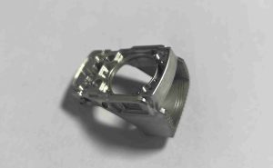
Recently, we worked on a batch of stainless steel (316L) components for a medical device company. The parts required thin walls (±0.05mm tolerance) and a mirror finish. Here’s how we approached it:
Challenge: Maintaining precision while preventing work hardening
Solution:
- Selected fine-grained carbide tools with specialized coating
- Used tools with polished flanks for better surface finish
- Implemented progressive wear monitoring every 50 parts
- Adjusted parameters based on real-time feedback
Result: 500 parts delivered with zero rejects and perfect surface finish
Your Next Steps Toward Smarter Tool Management
We understand that implementing a comprehensive tool management system can seem overwhelming. Here’s how to start:
For Beginners:
- Document Everything: Start tracking tool life and performance
- Educate Your Team: Share knowledge about tool wear signs
- Standardize: Create basic protocols for common operations
For Experienced Shops:
- Optimize: Fine-tune parameters based on data
- Specialize: Build expert knowledge in your niche materials
- Invest: Consider advanced monitoring systems
How We Can Help
At Lenchor Precision, tool management isn’t just something we do—it’s part of our precision manufacturing philosophy. Whether you’re machining prototypes or production runs, medical devices or industrial components, the right tool strategy makes all the difference.
Ready to improve your tool management? Contact us today for a consultation. We can:
- Review your current tooling strategies
- Recommend specific improvements
- Provide samples machined with optimized tooling
- Help you implement systematic tool management
Remember: In precision machining, your tools are your partners. Choose them wisely, listen to what they tell you, and they’ll help you create parts that exceed expectations.
Need help with a challenging machining project? Send us your drawings and material specifications. We’ll provide tooling recommendations and a quote. Visit our website or email us directly to start the conversation about precision manufacturing done right.