
The Hidden Truth: Your Design Decisions Directly Determine Machining Costs
At Lenchor Precision, we’ve analyzed thousands of CAD files and found a consistent pattern: up to 40% of CNC machining costs are determined by design choices that have nothing to do with part function. These “silent cost drivers” are often invisible to engineers but painfully obvious to machinists. The good news? Most are easily avoidable with basic awareness and a simple pre-submission checklist.
The High Cost of Small Mistakes: Real Examples from Our Shop
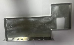
Case Study: The $450 Bracket That Should Have Cost $180
A client submitted a support bracket for a medical device. It looked clean in CAD, but contained three subtle errors that tripled its cost:
- Unnecessary 3D surfaces where planes would work
- Mixed tolerances without clear priority
- Non-standard hole patterns requiring special tooling
After implementing our DFM suggestions, the part cost dropped to $180 while maintaining all functional requirements. This isn’t exceptional—it’s typical.
The 7 Most Common (and Costly) CAD Errors
Error #1: The “Over-Designed” Surface
What it looks like: Unnecessary complex surfaces, organic shapes, or 3D contours where simple geometry would work.
Why it’s expensive:
- Forces 5-axis machining instead of 3-axis
- Requires specialized programming
- Increases machining time 200-400%
- Demands expensive ball-nose end mills
The Fix:
- Use planar surfaces whenever possible
- Apply complex surfaces only where functionally required
- Ask: “Would a flat surface with a chamfer work here?”
Example: A client designed an enclosure with flowing organic curves for aesthetic reasons. By converting side panels to flat surfaces with textured finishes, we reduced machining time from 8 hours to 2.5 hours.
![Image Suggestion: Side-by-side comparison of organic vs. simplified design]
Image Alt Text: CAD design optimization showing complex organic surfaces vs. simplified planar design for CNC machining
Error #2: Tolerancing Overkill
What it looks like: Applying tight tolerances (±0.01mm or better) to non-critical features.
The Cost Impact:
- Standard tolerance (±0.1mm): Baseline cost
- Precision tolerance (±0.05mm): +25-40% cost
- High precision (±0.01mm): +80-150% cost
Better Approach:
- Apply tight tolerances ONLY to mating/interfacing surfaces
- Use standard tolerances for non-critical features
- Clearly indicate which tolerances are critical vs. general
Pro Tip: Add a tolerance block to your drawing that clearly states:
- General tolerance: ±0.1mm
- Critical features: ±0.05mm (call out specifically)
- Special requirements: ±0.01mm (call out specifically)
Error #3: The “Non-Standard” Hole
Common Problems:
- Hole diameters that don’t match standard drill sizes
- Blind holes with flat bottoms
- Unusual thread specifications
- Deep holes (more than 10× diameter)
Cost Consequences:
- Requires special tool ordering (2-5 day delay)
- Higher tooling costs
- Slower machining speeds
- Higher risk of tool breakage
Optimization Checklist:
- All holes use standard drill sizes
- Through holes instead of blind holes when possible
- Standard thread specifications (metric/UNC/UNF)
- Depth ≤ 10× diameter for deep holes
Error #4: Neglecting Corner Radii
The Problem: Sharp internal corners that require small, fragile end mills and multiple tool changes.
The Reality:
- Sharp corners require undersized tools
- Small tools break easily and cut slowly
- Multiple tool changes increase machine time
- Impossible to achieve perfect sharpness anyway
The Solution:
- Add radii to ALL internal corners
- Match radii to standard end mill sizes (常见刀具半径: 0.5mm, 1mm, 2mm, 3mm, 4mm)
- Follow the ⅓ rule: Radius should be ≥ ⅓ of pocket depth
Example: A 10mm deep pocket should have at least 3mm corner radii.
![Image Suggestion: Diagram showing sharp corner vs. radius corner tool paths]
Image Alt Text: CNC tool path comparison showing efficient radius corner machining vs. problematic sharp corner machining
Error #5: Inconsistent Wall Thickness
The Issue: Varying wall thickness throughout the part, creating thin sections next to thick ones.
Why It Matters:
- Thin walls (<1mm for aluminum, <1.5mm for steel) require special techniques
- Varying thickness causes uneven heat distribution during machining
- Increases risk of vibration and poor surface finish
- Can lead to part distortion
Design Guidelines:
| Material | Minimum Wall | Recommended Range |
|---|---|---|
| Aluminum | 1.0mm | 1.5-3.0mm |
| Stainless Steel | 1.2mm | 2.0-4.0mm |
| Plastics (POM) | 1.5mm | 2.0-5.0mm |
Error #6: Ignoring Stock Material Sizes
The Mistake: Designing parts that don’t consider standard material dimensions.
The Waste:
- Requires custom material orders (3-10 day delay)
- Creates excessive material waste
- Increases material cost per part
Smart Design Practices:
- Design to standard plate/thickness sizes
- Consider nesting multiple parts on one plate
- Use our common stock dimensions:
- Aluminum plate: 6, 10, 12, 20, 25mm thickness
- Stainless plate: 3, 5, 8, 10, 15mm thickness
- Round stock: Standard diameter increments
Error #7: Missing Critical Information
What’s Often Missing:
- Material specification (not just “aluminum” but “6061-T6”)
- Heat treatment requirements
- Surface finish specifications (where critical)
- Deburring requirements
- Special handling instructions
The Consequence: Leads to quoting delays, clarification requests, and potential rework if assumptions are wrong.
Complete Drawing Checklist:
- Material specified with grade/temper
- All dimensions clearly labeled
- Tolerances specified (general and critical)
- Surface finishes called out where needed
- Thread specifications complete
- Any special notes included
Your Pre-Submission CAD Audit Checklist
Before sending any design for quoting, run through this 10-minute audit:
Geometry Review
- Are all internal corners radiused?
- Are walls consistently thick enough?
- Can any complex surfaces be simplified?
- Are holes standard sizes and through whenever possible?
Tolerance Analysis
- Are tight tolerances only on critical features?
- Are tolerance callouts clear and unambiguous?
- Can any tolerances be relaxed without affecting function?
Manufacturing Review
- Does design fit standard stock sizes?
- Are features accessible for machining?
- Are there thin sections that might vibrate?
- Are there deep cavities that need special tooling?
Documentation Check
- Is material fully specified?
- Are all views and sections included?
- Are notes clear and complete?
- Is there a revision history?
Advanced Optimization: Going Beyond Basics
For High-Volume Production
- Design for multi-part fixturing
- Consider special tooling investments
- Optimize for fastest possible cycle times
- Design for automated loading/unloading
For Medical Device Components
- Design for cleanability and sterilization
- Consider biocompatibility requirements
- Allow for validation and testing features
- Design for assembly and disassembly
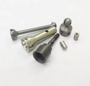
For Swiss-Turned Components
- Design for continuous machining
- Consider material waste optimization
- Design for secondary operation efficiency
- Consider bar stock diameter optimization
The Lenchor Precision DFM Process: How We Help
Step 1: Automated Analysis
Our system automatically flags:
- Non-standard hole sizes
- Sharp internal corners
- Thin wall sections
- Features requiring special tooling
Step 2: Engineer Review
Our experienced engineers:
- Identify optimization opportunities
- Suggest specific design changes
- Provide alternative approaches
- Estimate cost impact of changes
Step 3: Collaborative Optimization
We work with you to:
- Implement cost-saving modifications
- Validate functional requirements
- Create manufacturing-optimized designs
- Document all changes
Step 4: Continuous Improvement
We track:
- Cost savings achieved through DFM
- Common errors across clients
- Emerging best practices
- Industry-specific requirements
Real Impact: Measurable Results
Across our client base, implementing these DFM principles consistently delivers:
Cost Reduction:
- Average: 35% cost reduction
- Range: 15-60% depending on initial design
- Highest saving to date: 72%
Time Savings:
- Design-to-quote time: Reduced by 40%
- Manufacturing time: Reduced by 30-50%
- Overall project timeline: Reduced by 25%
Quality Improvement:
- First-pass yield: Improved by 45%
- Dimensional consistency: Improved by 60%
- Surface finish consistency: Improved by 50%
Getting Started: Your Action Plan
Immediate Actions (This Week)
- Audit one current design using the checklist above
- Share this guide with your design team
- Implement a pre-submission review process
- Request a DFM analysis on your next project
Medium-Term Strategy (Next Quarter)
- Create standardized design templates
- Develop internal design guidelines
- Train team on DFM principles
- Establish key supplier partnerships
Long-Term Excellence (Ongoing)
- Integrate DFM into your design workflow
- Measure and track cost savings
- Continuously update your standards
- Collaborate closely with manufacturing partners
Special Consideration: Addressing Your Search Concerns
For those searching for solutions to “hidden costs of poor machining tolerances” or needing a reliable “swiss turned parts supplier” for medical device prototypes, remember this: The most expensive tolerance is the unnecessary one, and the most reliable supplier is one who helps you optimize designs before machining begins.
Conclusion: Good Design is Good Business
The difference between an expensive part and a cost-effective one isn’t the machine shop—it’s the CAD file. By avoiding these seven common errors, you’re not just saving money; you’re building better parts faster, with higher quality and more predictable outcomes.
At Lenchor Precision, we believe the best manufacturing partnership starts with the best designs. We’re not just here to machine your parts—we’re here to help you design parts that are brilliant to manufacture.
Ready to optimize your designs and reduce costs? Send us your CAD files for a complimentary DFM analysis. We’ll identify specific cost-saving opportunities and provide actionable recommendations. Visit our website or email to start designing smarter today.